


Structural safety
Correct beam selection, spacing, bearing and reinforcement reduce the risk of cracking, excessive deflection and costly remediation.
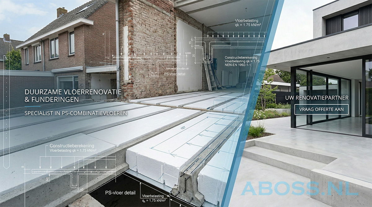
In Dutch residential work, a PS combination floor (also known as broodjesvloer, i.e. a beam-and-block floor) is a common choice: precast concrete beams with EPS infill blocks and a reinforced concrete topping. It is fast to install, thermally efficient and structurally robust — provided the engineering details are correct.
Aboss Bouwadvies delivers the required structural calculation and (where needed) structural drawings so the floor can be executed safely and remains coherent for review under the Bbl (Besluit bouwwerken leefomgeving).
Correct beam selection, spacing, bearing and reinforcement reduce the risk of cracking, excessive deflection and costly remediation.
Clear details for openings, edge beams, bearing points and connections to existing foundations, walls and load paths.
A consistent package: calculation + drawings + practical detailing for contractor, supervisor and permit or compliance pathways.
A beam-and-block floor consists of three primary components. Structurally, it works as a composite slab because the reinforced topping and beams act together and distribute loads across the floor plate.
The precast (reinforced) beams are the main load-bearing elements. They are supported on foundation beams, load-bearing walls or other structural lines. Their type and spacing are not “generic” — they must match the span, loading and support conditions.
EPS blocks are placed between the beams to form the floor volume and thermal layer. Benefits include high insulation, low self-weight and straightforward cutting to fit around edges and penetrations. Depending on the project (e.g. basement conditions or certain fire/acoustic requirements), alternative infill elements may be used.
A reinforced concrete topping is poured on top to create stiffness, diaphragm action and reliable load distribution. This topping is part of the load-bearing system; it is not merely a “finishing layer”.
In practice, a calculation is needed when you are changing the load-bearing floor system or introducing new load paths. Typical cases include:
The calculation typically defines: beam type, spans, bearing requirements, centre-to-centre spacing, reinforcement layout, topping thickness, and the detailing around openings and edges.
A combination floor is only as reliable as its supports. The beams must have sufficient bearing onto a structural support (foundation beam, wall, steel, etc.). In renovations, bearing seats are often formed by cutting pockets into existing masonry. Too little bearing can create local crushing, cracking and unpredictable load transfer.
Spacing drives both load capacity and deflection. You may hear “600 mm is standard” — but this is not a rule. The final spacing depends on span, beam type and imposed loads. In some cases, 480 mm spacing is used for higher loads, but the correct value must follow from the calculation, not from habit.
The concrete topping typically contains crack-control reinforcement. Its purpose is to limit shrinkage cracking, support composite behaviour and keep the floor’s diaphragm action continuous across the plan.
The topping must be thick enough to perform structurally, including cover to reinforcement and local robustness at edges. In many residential applications, an indicative minimum topping is around ≥ 30 mm. Total structural depth is commonly in the range of ± 200–250 mm, depending on beam height, insulation height and span.
Real floors include openings for drains, service ducts, inspection hatches and sometimes new stair openings. These areas require explicit detailing: trimming beams, reinforcement around penetrations, and edge stiffening. Un-detailed penetrations are a common trigger for defects and site disputes.
Note: exact requirements are project-specific (loads, spans, existing structure, support conditions, settlement risk). Aboss converts the real-world constraints into a clear, buildable calculation and detail set.
A frequent mistake is placing underfloor heating pipes inside the structural concrete topping. This is generally not correct: the topping is part of the load-bearing system and should remain structurally coherent.
This separation is not “theoretical”: it keeps the structural layer predictable and prevents later conflicts about drilling, channelling or repairs that compromise reinforcement and concrete cover.
Most failures are not caused by the floor system itself, but by incorrect assumptions during execution. Typical mistakes we see in practice include:
The result is often predictable: cracks, bounce, local crushing, and—equally important—disagreement between client, contractor and supervisors about “what was specified”. A proper calculation + clear drawings make the execution verifiable.
Aboss supports contractors and private clients with a pragmatic, execution-focused approach to beam-and-block floors. Our scope can include:
The goal is simple: a floor that can be built without improvisation, carries the intended loads, and remains defensible when reviewed by professionals.
If you send the items below, we can typically assess feasibility quickly and define the right calculation route. Where drawings are missing, clear photos + measured dimensions can be sufficient for an initial engineering intake.
Often yes, but suitability depends on span, available bearing points, existing load-bearing lines, crawl space conditions, moisture risk, and intended loads. We confirm feasibility during the intake and formalise it in the calculation and detailing.
600 mm is common in residential work, but it is not a universal rule. Span, imposed load, beam type and support conditions determine the correct spacing. A calculation reduces deflection risk and avoids later disputes.
Generally no. The topping is part of the load-bearing system. Underfloor heating should be placed in the finishing build-up (screed/finish layer) according to a correct floor build-up concept.
Yes. Where needed, we deliver structural drawings and connection details so execution and verification are unambiguous.
Timing depends on the completeness of input and the complexity (extension interfaces, openings, foundation constraints). Send the project data and we will respond with a realistic schedule and the required deliverables.
If you are building an extension or replacing an existing floor, start with the structural calculation. It gives you a defensible design, predictable execution and a dossier that holds up in practice.